Flow simulation

Visualization of flow and heat.


Our simulations enable:

  • Informed decisionsdeep understanding of the processes through visualization, even for complex or hard-to-measure operations
  • Improved collaboration – shared data foundation for technical exchange between development, testing, and production
  • Reduced development costs – fewer physical prototypes, shorter testing phases, lower effort
  • Higher quality – potential weaknesses are identified early and optimized virtually
  • Secured knowledge – simulations create a knowledge base for efficient follow-up projects

Used tools:

  • Siemens Star-CCM+
  • Ansys Fluent
  • Ansys EnSight
  • Converge
  • Siemens HEEDS
  • Beta Ansa
  • Siemens NX
  • Ansys Spaceclaim
Flow simulation projects

Mixing Processes (Container and Jet Nozzle Flow)

Benefits:

  • Visualization of mixing processes and identification of areas where there is little or no mixing
  • Determination of characteristic values of fittings (pressure loss, Kv value, etc.)
  • Calculation of the mixing time required to achieve a defined level of homogeneity
  • Prediction of the cleaning effect by analyzing shear velocity and degree of removal


Applications:

  • Design and development of fittings, nozzles, and valves
  • Food & beverage industry and pharmaceutical sector
  • Plant engineering and process engineering
  • Container construction and cleaning technology


For more information see below.

Other projects

Heat-Up and Cool-Down (Drying Process)

Benefits:

  • Plant optimization with regard to cycle times and energy efficiency during conversion measures or new planning
  • Virtual verification of permanent deformations caused by material mixes or cured adhesives
  • Virtual verification of baking temperatures for different applications, e.g., adhesive curing, cathodic electrocoating, NAD, wax, foams
  • Digitized systems create transparency – enabling more precise tenders and smooth communication


Applications:

  • Convection dryer/drying process
  • Autoclave
  • Infrared heating
  • Laminating
  • Afterheat effects in the engine


For more information see below.

Other projects

Multiphase Flow (Immersion Processes and Tank Flow)

Benefits:

  • Analysis of air entrapment during the immersion process
  • Virtual validation with regard to adhesive failure caused by immersion forces
  • Bath carryover and media mixing in the following plants
  • Plant optimization regarding nozzle arrangement and contamination tendency
  • Virtual validation and optimization of the product line regarding the formation of gas bubbles and bubble residues in the paint layer
  • Targeted separation of the effects of different parameters
  • Digitized systems create transparency – enabling more precise tenders and smooth communication


Applications:

  • Surface treatment & coating
  • Food and pharmaceutical industry (disinfection, cleaning, rinsing)
  • Virtual leak testing


For more information see below.

Other projects

Coating (Cathodic Dip Painting)

Benefits:

  • Plant optimization with regard to paint requirements and energy efficiency
  • Plant- and paint-specific calibration with deviations <5%
  • Virtual validation and optimization of the product line with regard to critical layer thickness
  • Cost-effective parameter studies in the pre-prototype phase before construction-> Target layer thickness


Applications:

  • Corrosion protection, e.g. cathodic dip coating
  • Electrochemical coatings & surface processes (galvanizing)
  • Battery technology & energy storage
  • Fuel cells & electrolysis


For more information see below.

Other projects

Thermomanagement (Co-Simulation)

Benefits:

  • Precise analysis of complex geometries (>1,000 components)
  • Optimized cooling performance through refined flow guidance
  • Coupled flow and heat simulation (co-simulation)
  • Temperature fields as input for FEM analyses
  • <10 K deviation from the measurement for 90 % of all measurement points


Applications:

  • Electrical and battery systems
  • Electronics cooling
  • Drives and robotic axes
  • Heating elements and control units
  • Engine thermal management
Other projects

Thermomanagement and Multiphase Flow (Oil Cooling in E-Motor)

Benefits:

  • Volume flow distributions in channels, spray holes, etc. while taking into account rotational movement (centrifugal effects) and gravity
  • Calculation of pressure loss in the oil circuit, optimization of pump design
  • Resistance moments due to shear and pressure forces
  • Degree of wetting (heat transfer coefficients)
  • Optional coupling to co-simulation for determining 3D temperature fields and hot spot analyses


Applications:

  • Oil-cooling E-motor
  • Lubrication of gears in gearboxes
  • Splash lubrication in the field of machining


For more information see below.

Other projects

Thermomanagement (Air Cooling)

Benefits:

  • Volumetric flow rate as a function of rotational speed (characteristic curves)
  • Visualization of flow paths and distribution enables the identification of areas with low cooling performance
  • Derivation of optimization measures for improved flow around components
  • Locating areas prone to high dirt accumulation


Applications:

  • Air cooling power electronics
  • Air cooling E-motor
  • Air cooling battery pack
  • Air cooling combustion engines


For more information see below.

Other projects

Core Skills Multiphase Flow and Contamination

Multiphase Flow (Spray Zone Carryover)


Before, between, and after immersion in coating processes, components or car bodies are cleaned in spray zones. The spraying process can cause additional liquid to enter the interior of the components. Since the alignment of the conveyor technology often remains constant during this phase, drainage can be examined and verified in the simulation.

Droplets and Solid Particles (Contamination Simulation)


Contamination simulations enable precise prediction of particle behavior based on flow fields. Both fine dirt particles (Lagrange) and coarser particles (Discrete Element Method) are analyzed. Particular attention is paid to the probability of impact and the blocking behavior of the particles. For maximum flexibility, a wide range of physical influences such as particle shape, size, and adhesive forces can be taken into account.

Coating (Cathodic Dip Painting)

To ensure optimum corrosion protection and precisely identify problem areas, painting processes such as cathodic dip coating (CDC) are supported by simulation. Multiphase simulation (VOF) and modeling of the painting process (e-coating) can be used to determine both the resulting layer thicknesses and air inclusions as well as their interaction, while the overset mesh approach allows the exact modeling of the dipping movement in the tank.


Calibration cycles are used to ensure a high degree of accuracy in terms of layer thicknesses.

Efficient meshing processes enable highly automated work flows, so that the most complex geometries can be prepared and calculated with millimeter precision in a comparatively short time.

Multiphase Flow (Condensation and Evaporation)

Phase transitions are of great importance, especially in the field of hydrogen engines, which can be modeled using suitable condensation and/or boiling models. In combination with fluid-film modeling, a complex multiphase problem can also be evaluated in a single-phase and thus comparatively quickly and cost-effectively. In addition, the determination of critical temperature ranges enables predictions with regard to possible icing.

Multiphase Flow (Immersion Processes and Tank Flow)

When carrying out immersion processes, various issues are evaluated using CFD and FE calculations. For example, when components are immersed and removed, the resulting pressure differences are investigated, which cause external and internal parts to be pressed together or apart. This entails the risk of plastic deformation and adhesive failure. Pressures, forces, component movements and deformations can be analysed and optimized in order to minimize potential risks.


After the dipping process, residual liquids often remain in the dipped components. A VOF simulation is used to prevent these residual liquids from being carried over into subsequent tanks or burning in the dryer. This determines the remaining liquids, which can then be removed through suitable openings or movements of the conveyor system.


The simulation also provides valuable insights into the flow situation in the tank. Based on the prevailing process conditions, targeted measures can be taken to optimize the flow around the components in order to make the entire process more efficient and reliable.
Core Skills Thermomanagement

Thermomanagement (Co-Simulation)


Our specially developed co-simulation is used for calculation methods in which the coupling between two continua with different time scales must be evaluated. This approach reduces calculation time while maintaining the same quality of results. Examples include couplings between transient air flows and solid components that exhibit very sluggish thermal behavior. Cooling and heating processes can also be evaluated cost-effectively using this approach.

Thermomanagement and Multiphase Flow (Oil Cooling in E-Motor)

In the course of e-mobility, calculation methods are needed to calculate the cooling performance on the windings of electric motors. Due to the different state variables of the oil, these are highly complex calculations. Rotating oil jets break down into smaller and smaller droplets that form oil clouds because of the speed of rotation and the impact on the windings. An oil film forms on the windings and the walls, which ultimately collects at various points. Simultaneously, heat transfer and electromagnetism take place.


The ability to combine different hybrid multiphase models enables efficient evaluation within a single simulation. Heat transfer and electromagnetism can be added as well.

Thermomanagement and Multiphase Flow (Lubrication of Gears, Splash Lubrication)


The lubrication of gears in gearboxes as well as the splash lubrication in the field of machining are typical applications for complex multiphase simulations with moving parts. Here, wetted surfaces, drag losses, heat dissipation and other parameters can be determined in order to avoid wear problems or to understand existing damage patterns.


Continuous quantities of oil from the oil sump or oil jet are finely atomized and distributed by rotating parts. Precise numerical discretization and modelling of adhesion properties enable the recording of even the smallest quantities of oil and their interaction. In addition, multiphase simulations can be used to model filling processes, such as those that take place in cooling circuits or batteries, for example to localize and eliminate air pockets.

Heat-Up and Cool-Down (Drying Process)

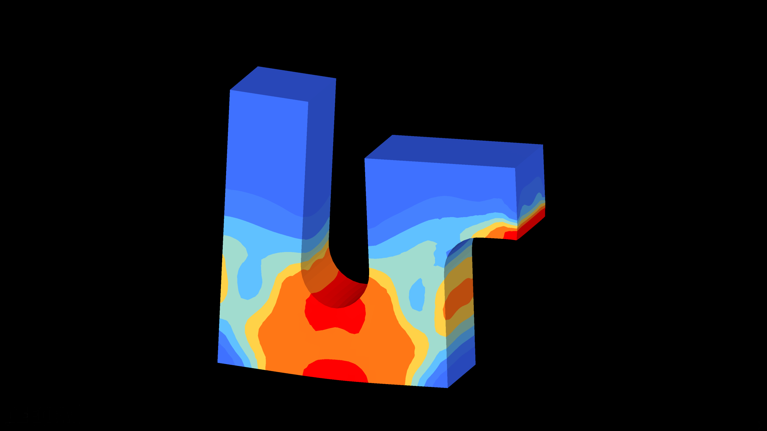
In a drying process, components are dehumidified through the use of thermal methods. For example, in a convection dryer, a car body is heated to a target temperature, which depends on the application. This is necessary to burn in process materials. By using co-simulation, the process can be modeled with different time scales, which enables the movement through the oven system and the simultaneous heating of the components. The movement in the fluid (calculation region stationary) is solved, while the heat conduction in the component (time-dependent/transient) is calculated in a second region (solid). This method enables a precise evaluation in order to economically optimize the product and system with regard to target conditions and energy efficiency.


And finally, with a mapping method the component temperatures can be projected onto finite element meshes, which serve as boundary conditions for a thermomechanical distortion calculation.

Thermomanagement (Air Cooling)

The key to a long service life of power electronics lies in their effective cooling in order to maintain the maximum permissible temperatures. For the development and optimization of cooling systems, calculation methods are required that can model all heat transfer mechanisms (heat conduction, free/forced convection, heat radiation) as well as active cooling air flows, often generated by fan wheels. Rotating components can be modeled using a simplified, stationary and very efficient moving reference frame (MRF) approach.


Transient methods are physically more accurate and offer advantages in terms of the quality of results, but require more computing time. Transient effects can also be resolved using the actually rotating volume mesh.


Cooling calculations enable statements to be made about cooling air volumes, component temperatures and relevant heat paths. This allows the complete understanding of the system and the identification of optimization potential.

Further Core Skills

Mixing Processes (LES)


When mixing single-phase substances, we rely on the Large Eddy Simulation (LES) in our calculation methods in order to model the turbulent behavior with high accuracy while maintaining a balanced relationship to the simulation costs.

Flow Machines (Compressors, Turbines)

Both stationary and transient calculations are carried out for turbocharger and compressor simulations. Characteristic diagrams are generated by the simulation. In addition, the limit ranges can be defined in which the surge and choke lines are reached. It is also possible to evaluate the thermal behavior and localize failure weak points.

Mixing Processes (Container and Jet Nozzle Flow)


Jet mixing nozzles are fittings that enable agitator-free mixing of large tanks, for example in the food industry, based on the principle of a water jet pump. Their advantage lies in their suitability for the CIP process (Cleaning-in-Place), where the system can be cleaned hygienically in an automated manner without manual intervention. For the design and implementation in the plant, it is important to understand both the operating principle of the nozzle inside the vessel and its pressure drop during use.

By means of a series of CFD simulations, it is possible to efficiently and relatively cost-effectively investigate the entire product range of several nominal diameters under different load cases in various tanks. By visualizing the flow the fitting can be optimized with respect to pressure drop and secondary flow.

Structural simulation

Bringing structures into shape.


Our simulations enable:

  • Informed decisionsdeep understanding of the processes through visualization, even for complex or hard-to-measure operations
  • Improved collaboration – shared data foundation for technical exchange between development, testing, and production
  • Reduced development costs – fewer physical prototypes, shorter testing phases, lower effort
  • Higher quality – potential weaknesses are identified early and optimized virtually
  • Secured knowledge – simulations create a knowledge base for efficient follow-up projects

Used tools:

  • Simulia Abaqus
  • Ansys LS-Dyna
  • DEFORM
  • Simufact Forming
Structural simulation projects

Forming Simulation Wire Winding

Benefits:

  • Visualization of needle motion and winding geometry
  • Analysis of bending and tensile stresses along the wire
  • Adjustment of needle geometry based on realistic contact conditions
  • Provision of real geometries for thermal analysis (CHT)


Applications:

  • E-motors (needle winding, robotic winding, manual winding)
  • Coil production for sensors, actuators, ignition and induction coils
  • Coil winding in medical engineering (e.g. micromotors)
  • Seat heaters, film heaters, or tool heating systems


For more information see below.

Other projects

Fluid-Structure Interaction

Interactions between fluids and freely moving solids are modeled using Dynamic Fluid Body Interaction simulations. Objects can be moved by nascent disturbance variables such as gravity, flow forces, static friction, etc. Examples of possible applications include immersion movements of ships, marine propellers and turbines of hydroelectric power plants or pneumatic valves.


In addition, the deformability of the body can be taken into account using fluid structure interaction simulations. This modeling method enables complex calculations, for example in the field of medical technology for heart valves, but also for the deformation of solar modules that are influenced by the wind.

Other projects

Multiphase Forming Processes

Multiphase forming processes are forming processes that are carried out in several consecutive process steps in order to gradually shape a workpiece into the desired form. Different forming methods (bending, embossing, etc.) can be combined or a single process can be used in multiple stages.


Forming simulation provides information on material flow, process forces and occurring stresses and supports the design and optimization of processes.

Other projects

Thermomechanical Distortion

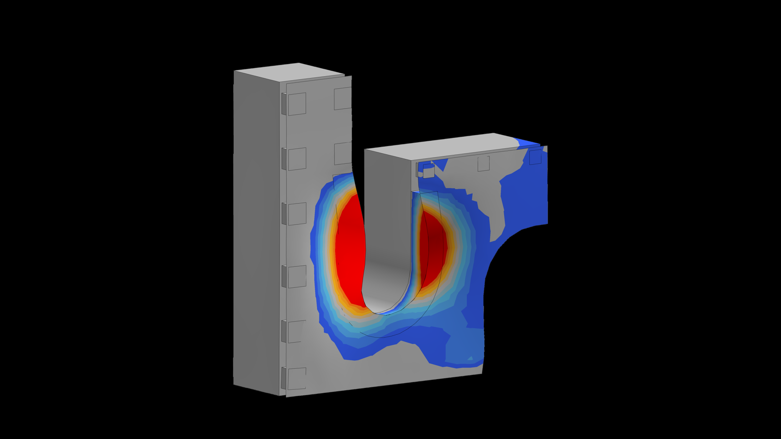
During a drying process, high temperature gradients between the components lead to different expansion movements in the material mix of an assembly. These movements can be »frozen« by hardening adhesives, resulting in permanent deformations.


Based on the simulation, the joining technology and the components are optimized in critical areas. A detailed evaluation of the joining technology is also possible. The required temperature boundary conditions are determined by a previously performed CFD simulation or measurements and projected onto the FE mesh.

Other projects

Examples Mechanical Deformation Body-In-White

Battery assembly

The installation of the battery assembly generates deformations in the entire shell. Especially unfavorable tolerance fields of the battery and the shell can further increase this deformation. It is essential to prevent the deformation in different tolerance positions. Furthermore, forces in the screw connections resulting from the tolerance field can be determined.

Joining simulation

When assemblies are joined using thermal and mechanical joining processes, such as spot and laser welding, clinching or roller hemming, stresses and plastic deformations occur. Joining simulation allows these processes to be analyzed in detail. It enables the prediction of stresses and deformations so that targeted optimization measures can be developed for individual components and equipment. This allows existing production problems to be identified and solved efficiently. In addition to digital product development, joining simulation helps to minimize the use of hardware and increase quality.

Skid support

The positioning and implementation of the vehicle body on different skids creates changing deformation states due to its own weight. Attachments (weight variations) that are added during the development process can additionally be secured.

One-sided lifting

Lifting the hood on one side causes the assembly to twist. This is indicated by a narrowing gap between the mudguard and hood. A collision or contact must be avoided.

Fixed glass roof

The fixed glass roof is joined to the shell using an adhesive connection. It is inserted at defined points using grippers.
The stresses and absolute deformations of the adhesive must be prevented during the assembly process and the gripper positions optimized. The glass roof and the mounting on the shell are examined and secured.

Rolling

Rolling is a forming process in which a workpiece is plastically deformed by the movement of rollers and can be used to manufacture assemblies. Simulations deepen the understanding of the process and analyze the influence of critical process parameters on the quality of the assembly. In addition, experiments for the quantitative evaluation of the assembly can be simulated so that direct validation is possible.

Further Core Skills

Wire winding (Forming simulation)

In an example of massive forming wire winding, the wire wrapping process of a winding machine is simulated. Such simulations are used for CAD modeling of the wires, which prevents errors during manual winding creation in CAD from occurring. In addition, the simulation enables the actual process of the automatic production machine to be modeled digitally. This saves costs on the one hand by shortening the design time, and on the other hand digitally depicts how an electric motor coil winding machine works.

Process automation

The diversity of our calculation methods requires flexible and adaptable automation solutions that are tailored to the individual needs of our customers. We develop independent programs that automate pre- and post-processing for CAE applications and are visualized for the end user with a user-friendly graphical interface.


Through targeted process automation we increase efficiency, reduce costs and minimize errors. In this way, we enable reliable delivery dates and the highest quality standards for all our customers.

Used programming languages:

  • JAVA
  • Python
  • Bash-Scripting
  • C
Process automation

Toolbox

We have developed a universal process as part of a ZIM project due to the demands for high flexibility and great adaptability of our automation. Our employees are supported in the application of this process by our in-house simulation assistant. The wide range of included tools is supplemented by the following functions:

  • Automatic geometry import and naming according to nomenclature
  • Automatic setup (specification of boundary conditions in Excel or JSON format)
  • Automatic Power Point evaluation for subsequent calculations


Calculation methods that are in high demand and whose development has been completed can be almost completely automated on the basis of the functions used in the simulation assistant.

Further examples

EnSight Toolbox

The EnSight Toolbox supports employees in efficiently importing simulation results into Ansys EnSight and automating the creation of post-processing objects (such as section planes, vector displays, isosurfaces and isovolumes, etc.). The data sets are imported in a process-specific manner via a GUI, whereby up to six simulation results can be compared with each other.


Furthermore, a JSON importer enables scenes from Siemens Star-CCM+ to be reproduced in EnSight. The created scenes are saved in States, allowing them to be customized by employees.

ANSA Batch-Mesh

The ANSA Batch-Mesh function enables employees to automate and optimize the meshing process for simulations. This feature allows large volumes of geometries to be processed efficiently and consistently, improving the quality and accuracy of simulation results.


Through a user-friendly GUI, various mesh parameters and settings can be configured to meet the specific requirements of each simulation. The Batch-Mesh function also supports the parallel processing of multiple geometries, significantly reducing overall processing time.